
A gas detector controller typically uses 4-20mA output or RS485 communication to transmit gas concentration data and connect with monitoring systems. Proper wiring is essential to ensure stable signal transmission and reliable operation.
This guide explains how to complete the 3-wire 4-20mA connection and 4-wire RS485 connection for the GD900-32C gas detector controller.
Watch the complete video: Gas Detector Controller 4-20mA & RS485 Wiring
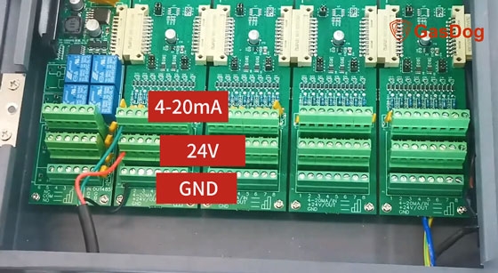
3-Wire Connection for 4-20mA Output
The 4-20mA output is commonly used for analog signal transmission between the fixed gas detector and external control systems, such as PLCs or alarm panels.
To complete the 3-wire 4-20mA wiring:
- Open the front cover of the gas detector controller and locate the internal terminal blocks.
- Pass the 3-wire cable through the external cable gland and insert it into the controller housing.
- Connect the green wire to the 4-20mA output terminal, then tighten the screw to ensure a secure connection.
- Connect the red wire to the 24V power terminal and tighten it firmly.
- Connect the black wire to the GND (ground) terminal.
- Check that all terminals are properly tightened and that the wires are securely fixed.
Once all connections are completed, the 3-wire 4-20mA output wiring is ready for use.
4-Wire Connection for RS485 Communication
RS485 communication allows the gas detector controller to communicate digitally with monitoring systems, providing more reliable data transmission over longer distances.
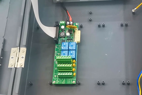
To complete the 4-wire RS485 wiring:
- Feed the 4-wire cable through the external cable gland and tighten the gland to secure the cable.
- Connect the red wire to the 24V power terminal and the black wire to the GND terminal for power supply.
- Connect the green wire to the RS485 A terminal.
- Connect the yellow wire to the RS485 B terminal.
- Make sure all wiring points are firmly connected before closing the controller cover.
After completing the wiring, the RS485 communication connection is ready for communication with external monitoring equipment.
Conclusion
Correct wiring of a gas detector controller is important for accurate gas monitoring and stable system operation. Whether using 4-20mA analog output or RS485 digital communication, ensure that each wire is connected to the correct terminal and securely tightened. A properly installed wiring system helps the gas detector provide reliable gas concentration monitoring for industrial and commercial safety applications.


