
How to Wire a Fixed Gas Detector?
This comprehensive guide provides detailed instructions for wiring GasDog fixed gas detectors, including the GD300 and GD700 series. It covers precise wire connection procedures, expert recommendations on optimal cable selection, in-depth guidance on wiring interfaces, practical application examples, and clear connection diagrams for integrating multiple detectors. Following this professional wiring guide ensures a safe, efficient installation process, guaranteeing accurate and dependable gas monitoring in diverse operational environments.
Wire Connection Instructions
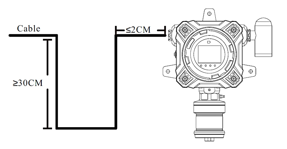
For outdoor installations subject to dust, rain, or water mist, dust-proof, moisture-proof, and rain-proof treatments, such as the installation of a rain cover, are required. The wiring configuration depicted in the image below is recommended to prevent rainwater from reversing and damaging the internal circuit board of the fixed gas detector.
Warning:
- For your safety, ensure that all wiring is operated by qualified professionals. Improper installation may lead to an electric shock or serious damage to the gas detector.
- During the wire connection process, it is forbidden to power on.
Cable Selection
- RS485 transmission cable: Please use shielded twisted pair cable, the theoretical maximum transmission distance is about 1200m, and the actual transmission distance is less than the theoretical value. If long-distance transmission is required, signal transmission repeaters can be used, but no more than 8 repeaters on one wire (repeaters need to be purchased separately).
- 4-20mA transmission cable: Please use shielded cable with a core diameter of 0.75mm or more.
Note: The transmission distance of 4-20mA is determined by the load resistance. The maximum load of this detector is 500Ω (when powered by 24V). The load resistance includes the input resistance of the control system (controller, PLC, DCS, etc.) and the internal resistance of the cable. Under the condition that the input resistance of the control system remains unchanged, the transmission distance is calculated using the following formula:
Reference distance = (500-Rc) ÷ Rm
- Rc: input resistance of the control system
- Rm: resistivity of transmission cable
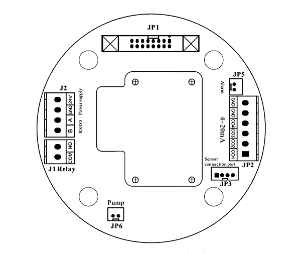
Wiring Interface
- Left J1: the relay control interface: COM (common end), NO (normally open end).
- Left J2 Terminal: The interfaces from top to bottom are: 24V (DC power-positive), GND (power ground), A (RS485A-positive end), B (RS485B-negative end).
- Right JP5: Alarm light interface
- Right JP2 Terminal: The 4-20mA interface
- Right JP3 Terminal: The digital probe interfaces from top to bottom are: GND (power ground), followed by sensor channels COM4, COM3, COM2, and COM1.
Application Example
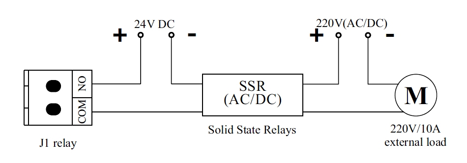
When the fixed gas detector detects harmful gases at the site and the concentration reaches the alarm threshold, the detector's screen and indicator lights will signal an alarm. If an optional alarm light is installed, both audible and visual alarms will be triggered. At this point, the relay's normally open contact closes, completing the circuit (as shown in the figure below), which can activate a ventilation fan or the alarm system.
Note:
- When the instrument alarms, you must leave the workplace as soon as possible. Otherwise, serious personal injury or personal injury may be caused.
- Please recalibrate and check the detector afterwards to avoid the expansion of equipment errors and cause false alarms.
Multiple Fixed Gas Detectors Connection Diagram
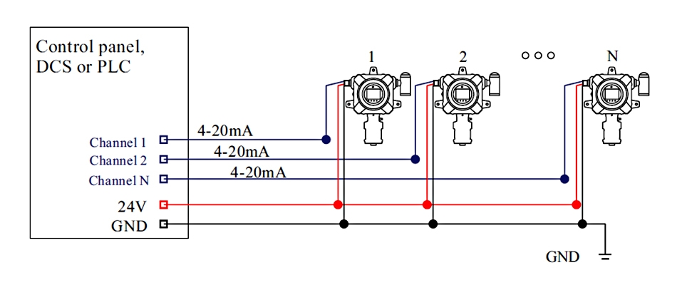
4-20mA current signal output mode and RS485 digital signal output mode are different in wiring; the following example power supply connection mode is for reference only, and the power supply mode can be selected according to the actual situation during installation.
A. 4-20mA current signal output connection mode. (must be grounded together)
A. 4-20mA current signal output connection mode. (must be grounded together)
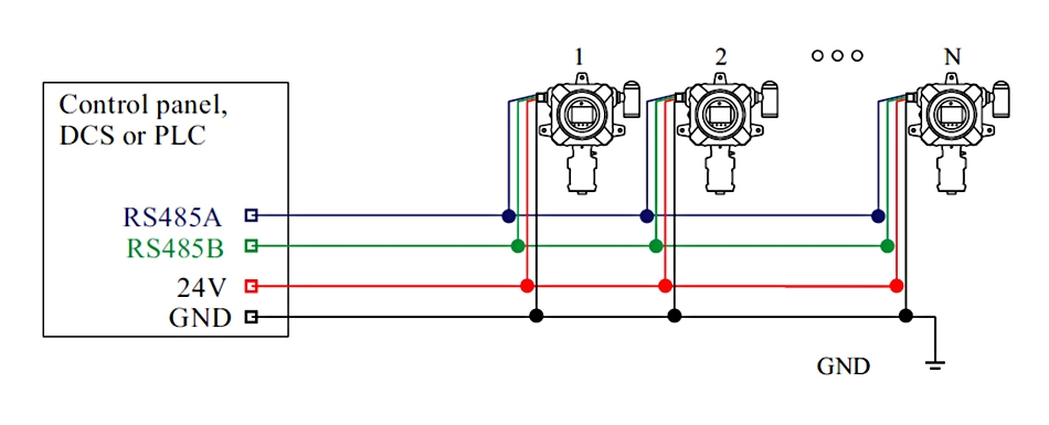
B. RS485 digital signal output connection mode 1. (can be independently grounded)
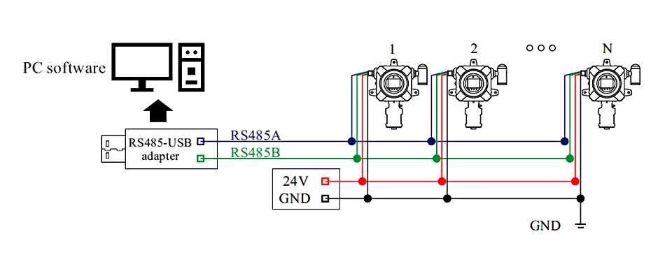
C. RS485 digital signal output connection mode 2. (can be independently grounded)
Following this detailed wiring guide ensures the proper installation and optimal functionality of your gas detector and monitor, whether used in industrial, commercial, or residential environments. If you encounter any challenges during installation, our professional technical support team is ready to assist. Rely on GasDog for dependable and accurate gas detection and monitoring solutions, tailored to your specific needs.


